TCP/IP
The evoVIU camera supports communication via the TCP/IP protocol to exchange data with other devices in the network. It can act as both a client and a server, depending on the application.
In client mode, the evoVIU camera establishes a connection to an external server. Once a connection is established, the camera can send specific data such as image information or metadata – for example, to a central control unit or an evaluation system. This mode is particularly suitable when the camera is to actively transmit data to a known destination.
In server mode, on the other hand, the evoVIU camera waits for incoming connections. External clients, such as machine controllers or PCs, can connect to the camera to query data or trigger actions (e.g., image capture). This mode is ideal when the camera is to respond passively to control commands.
Both modes are based on stable, connection-oriented TCP/IP connections. The selection of the operating mode depends on the system architecture and the requirements of the application.
Configuration is carried out directly via the evoVIU web interface, whereby the IP address, port, and transmission direction must be clearly defined.
Connection Parameters
TCP Server
Parameter | Type | Unit | Explanation | Example |
|---|---|---|---|---|
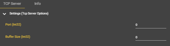
Port | Integer | The port address used to access the evoVIU as a TCP server on the network. Please note that certain ports must be approved by IT when integrating the camera. | 7778 | |
Buffer Size | Integer | Byte | The size of the input buffer. The decisive factor here is the size of the telegram. It is generally advisable to always provide the buffer with some leeway. If the buffer is too small, several events will occur until all data has been sent. | 5000 |
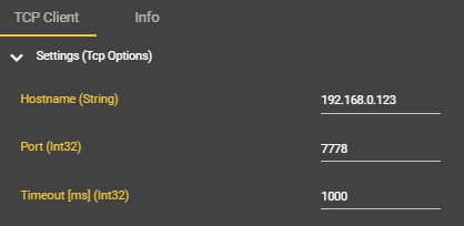
TCP-Client
Parameter | Type | Unit | Explanation | Example |
|---|---|---|---|---|
Hostname | String | The broker's destination address. This is usually provided by IT. | mytcpserver.mydomain.de | |
Port | Integer | The port address of the TCP server in the network. Please note that certain ports must be approved by IT when integrating the camera. | 7778 | |
Timeout | Integer | ms | After this time, it stops sending to the client with an error message. | 1000 |
Workflow Setup
Difference between TCP server and TCP client
The evoVIU camera can be operated either as a TCP server or a TCP client:
In server mode, the camera waits for incoming connections from a control device or PC. The external device establishes the connection to the camera.
In client mode, the camera actively connects to a specified server (e.g., PC or control center) via IP address and port.
The advantage of the evoVIU camera system is that any number of servers and clients can be connected. The only important thing is to adjust the event scheduling and ports accordingly.
Creating a TCP server - step by step
The TCP server is only visible to other participants in the network once the workflow has been started. When the workflow is stopped, the connections are automatically terminated. It must be checked whether the participants automatically reconnect to the camera when restarting.
After creating a TCP server, the Event Node Receive Bytes (TCP Server) can be added to the workflow. This is sent to the event nodes when a message is received from the client and can be used from there for further processing.
In Workflows, go to Components and select ➕.
Look for “TCP Server”.
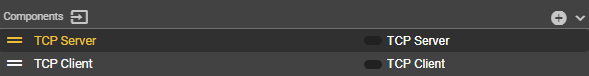
A new component called “TCP Server” appears.
The name of the component can be changed. However, it should be noted that you will then have to search for the changed name instead of TCP Server.
Enter the access data and parameters according to your preferences.
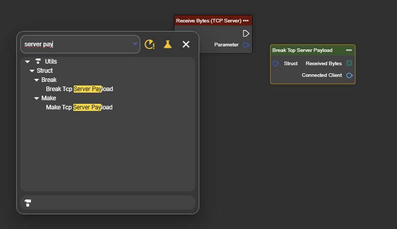
Right-click to open the context menu and search for “TCP Server” under “Events”.
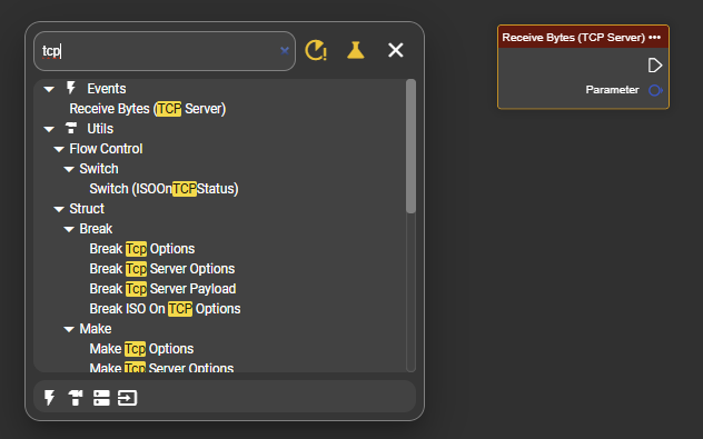
Select the node “Receive Bytes (TCP Server)”.
To make the data accessible, also search for “Break Tcp Server Payload” in the context menu and connect the output “Parameter” of the event to the input ‘Struct’ of “Break Tcp Server Payload”.
The event node is ready to receive data.
Extending the TCP server with response to client - step by step
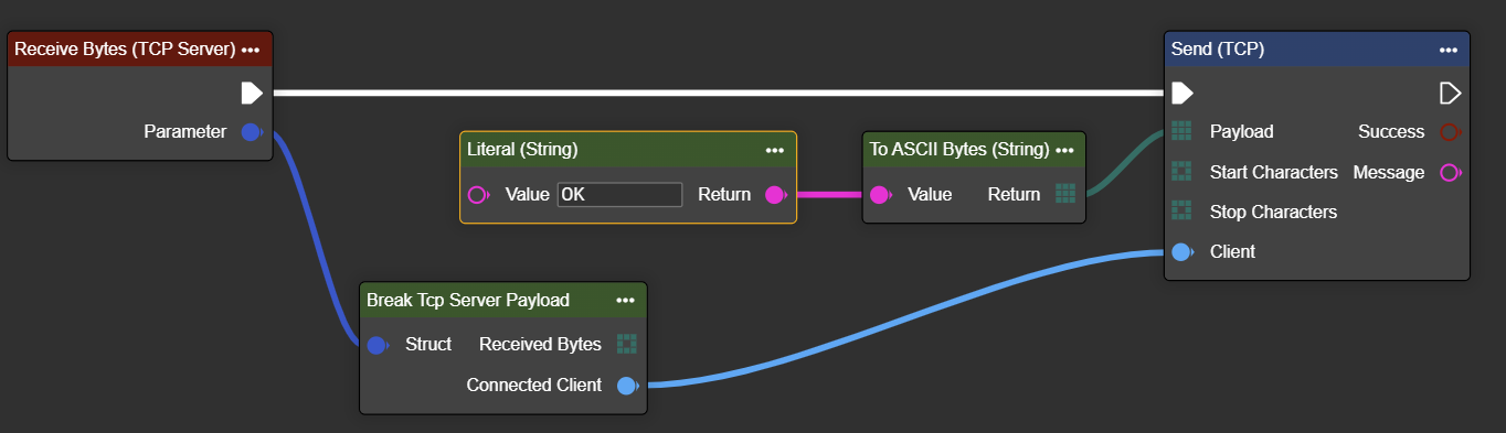
Follow all steps up to step 7. In addition to the received bytes, the “Break Tcp Server Payload” also contains the output “Connected Client.” With this, you can send a response after processing the data directly via TCP Send without creating a TCP client component. The exact use of TCP Send is explained in the following chapter. However, a separate component is created for this.
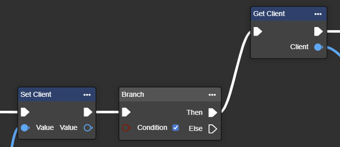
Example 1 shows a response that is possible directly in the execution path. Example 2 allows you to temporarily store the connection and call it again at another point in the code, for example after a branch (If / Else).
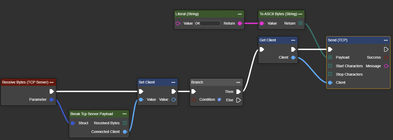
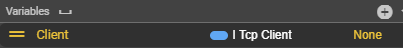
To use a variable to maintain the “Client” connection, a new variable of type “I Tcp Client” must be created under Variables.
Before the flow control element, the connection can be established with “Set Client” and then retrieved again after the flow control element with “Get Client”.
General information on using the TCP server
The server only starts when the workflow starts and ends when the workflow ends.
If the input buffer “Buffer” is set too low, the event will be triggered several times in succession until all data has reached the camera. This should be avoided to ensure a smooth process.
No start/stop characters are required for the TCP server. Simply sending the desired data is sufficient.
Usage - Splitting the data in “Receive Bytes (TCP Server)”
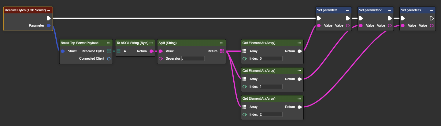
Splitting the data telegram using “Split String”
The Split String can be used to split the incoming data telegram into different parameters.
Example:
Example telegram from client:
Paramter | Telegram of Client | Variable in camera |
|---|---|---|
Varinat | A9472;2025-01-20 14:15:16;True | A9472 |
Time | 2025-01-20 14:15:16 | |
UseMeasure | True |
As soon as the data arrives at the camera, it is converted into ASCII characters and split using split string via the separator and sent to the individual variables.
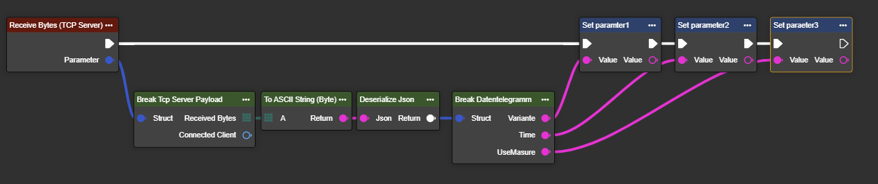
Splitting the data telegram using “Deserialize JSON”
An incoming JSON structure can also be broken down using a “Struct” and made usable for further steps.
Paramter | Telegram of Client | Variable in Camera |
|---|---|---|
Varinat | { | A9472 |
Time | 2025-01-20 14:15:16 | |
UseMeasure | True |
To do this, create a structure under “Structs”.
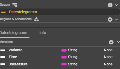
Integrate the structure into the workflow. A Boolean could also be used for “UseMeasure”.
Creating a TCP client - step by step
In Workflows, go to Components and select ➕.
Search for “TCP Client”.
Enter the access data and parameters according to your endpoint.
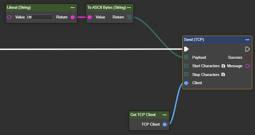
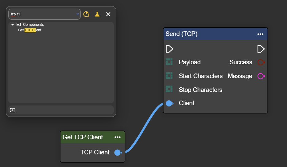
Right-click to open the context menu and search for “Get TCP Client” under “Components”.
Also select the “TCP Send” node and connect both nodes to each other.
To send data, link the payload to the desired transmission data. The “Literal String” node is only mentioned as a data example in this case. Any byte format can be sent.
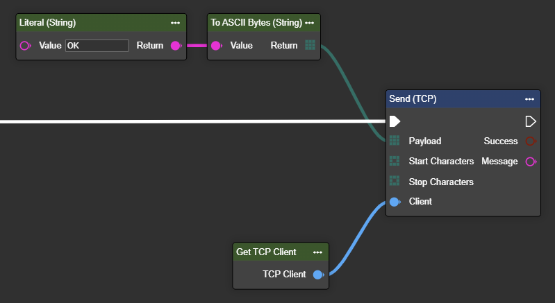
The event node is ready to send data to the corresponding endpoint.
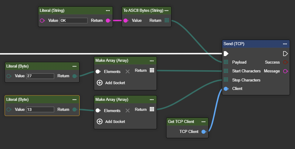
Extension of “TCP Send” with start/stop characters
If you want or need to include control characters as start/stop characters in your telegram, you can do so using the “Start Characters” and “Stop Characters” inputs. The control characters can be read from any ASCII table. The decimal values are written to the literal bytes. Example ESC = decimal 27
There are two options for this:
Setting start/stop signals via workflow inputs
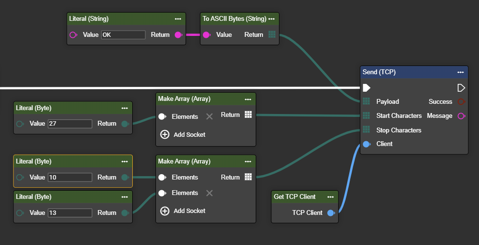
Setting the start/stop characters via Settings in the “TCP Send” node
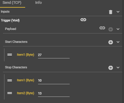
Flow as in example 1, but the start/stop character data is set in the Details tab of the node. The settings made in the node are indicated by the “Value Configured” icon.