Logic
The logic part
In the top app bar, you can switch between the individual higher-level components of the workflow. When you open a workflow, you are usually in the logic section, which can be identified by the title “Logic” after the list of workflows and the name of the selected workflow.

In the logic area of the workflow, you configure the workflow, which consists of nodes (node elements) and connection elements. The workflow is processed sequentially and presents the desired results in the output window. In addition, certain nodes allow you to define actions for processing the results after they have been evaluated.
Before you start creating a workflow, it is important to understand the various windows in Workflow Logic.
Output Tab
This window displays the results of the workflow. When a workflow is started, the output window tracks exactly what is happening in the background. At the beginning, the trigger of the workflow is usually displayed, i.e., the event that starts the workflow. After that, the activated nodes are listed. If these nodes deliver results, these are also visible in the output window. In the event of workflow errors, these are also displayed in the output window for the user.
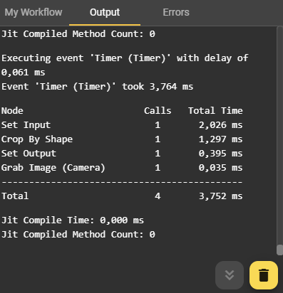
By clicking the Delete button in the Output window, you can remove previous information. This can help you maintain a better overview, especially when a lot of information is displayed. Clicking the button to the left of it always takes you to the latest results.
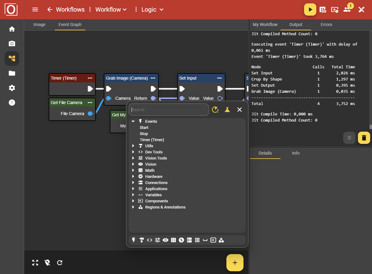
Event Graph Tab
This is the area for the visual representation of your workflow. Here you place the required nodes and connect them to each other.
Adding Nodes
To create a node, you can either right-click in the Event Graph section or use the plus icon in the lower right corner. This opens a dialog box with all available nodes. Use the search function or navigate through the various categories to find the appropriate node. The documentation for all nodes can be found in the application in the Details tab once you have selected a node. After selecting the node, the dialog box disappears and the node appears in the Event Graph window.
Removing Nodes
If you want to remove a node, click on the three-dot menu in the node and select the “Remove” option. You can also remove the selected node using the key combination ‘Ctrl’ and “Del”.
Connecting Nodes
To connect nodes, click on the connection elements of the nodes, drag them with the mouse to the next node, and click on the connection element again. This creates a line between the two nodes.
It is important to note that not every node can be connected to every other node. The data types must always match. This can be identified by the colors and symbols of the connection elements. For example, you cannot connect an image output to a string input element, as this is directly prevented. The symbols and colors assigned to each file type can be identified by hovering over the symbols.
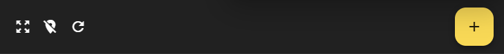
Bottom App Bar
In the bar at the bottom of the screen in the Event Graph tab, there is a yellow button on the right-hand side for opening the context menu. You can then use this menu to add nodes. You can also use this bar (arranged from left to right) to reset the zoom, show or hide the minimap, and reload the graph.
Errors Tab
Ideally, the Errors tab should be empty. However, if errors occur in the workflow, they will be listed here. Each error is displayed with the corresponding location and instructions for fixing it. Errors may occur in the schemas under “My Workflow” and must be corrected there. You can see that errors are present if there is a red exclamation mark icon next to the Errors tab.
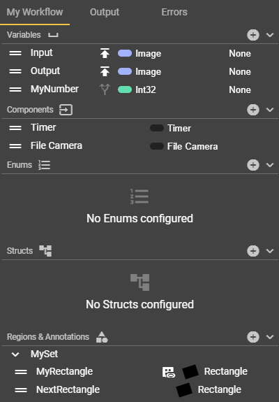
My Workflow Tab
In the “My Workflow” section, there are four categories of user-defined nodes:
Variables
Components
Enums
Structs
These can be created individually and integrated into the workflow using Get and Set nodes. These user-defined nodes can be edited by clicking on them. This causes the corresponding node to appear in the window at the bottom right and offers various setting options depending on the type.
To create a new custom node, click on the plus icon of the desired custom node. For variables, enums, and structs, your new node will appear directly in the list, while for components, you can select which component you want to add from a drop-down menu. Variables are global and therefore suitable for data exchange between events.
You can give the nodes individual names by clicking on the current label. Entries can be deleted again by clicking on the trash can icon. For variables, select the type by clicking on the current type and selecting your desired type from the drop-down list. Once a custom node has been added to the list, it can be added to the event graph.
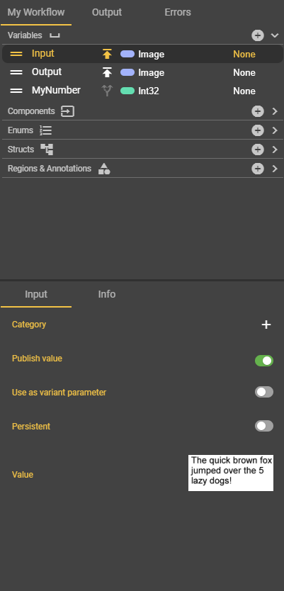
Variables
You can store any relevant data type that is required for your workflow as a variable. This includes primitive data types such as strings, enums, booleans, or integers, as well as created enums or structs. Select the appropriate data type from your list and specify whether it is an array or not. In the corresponding Custom Node window, you can enable or disable the “Publish Value” field. If you enable this, the values of the “Values” will be displayed and passed on.
Components
As the name suggests, user-specific components can be added here. One extremely popular component is Image Source. If you add this component, for example, you can select an image source configuration to ensure perfect image capture while executing your workflow.
Enums
Create enums by clicking on the plus icon. Enums are a data structure that allows you to define a set of values. You can define these values in the window at the bottom right. Click on the plus icon in the window with the name of your enum and create as many members (values) as necessary.
Nodes in which enums are used include, for example, the To String, Literal, or Select nodes. To add an enum to the event graph using the Set or Get method, you can store your user-defined enum in a variable. To do this, specify your enum as the data type of your variable.
Structs
Click on the plus icon to create structs. Structs are data structures that allow you to group different data types into a single unit. You can also add multiple members to structs using the plus icon. For these, you can specify a data type and a container. Nodes that use structs are the break and make nodes.
To add a struct to the event graph using the set or get method, you can store your user-defined struct in a variable. To do this, specify your struct as the data type of your variable.
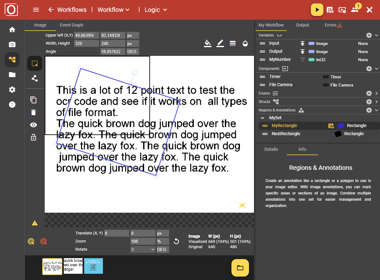
Regions & Annotations
Create annotation sets and annotations by clicking on the plus icon. Annotations are shapes that you draw on an image area so that they can be used for further processing.
To use an annotation in the workflow, add the Get node of the respective annotation to the workflow. You can then connect it to other nodes, provided that the permitted connection types match.
Further information on configuring annotations can be found in the Image Editor section.
Details Tab
Once you have selected a node or element from the My Workflow tab, you can enter specific information or configure details. The content of the Details tab varies greatly depending on your selection.
Info Tab
The Info tab provides detailed explanations of the individual components and how nodes and components work. This information is accessible at any time.
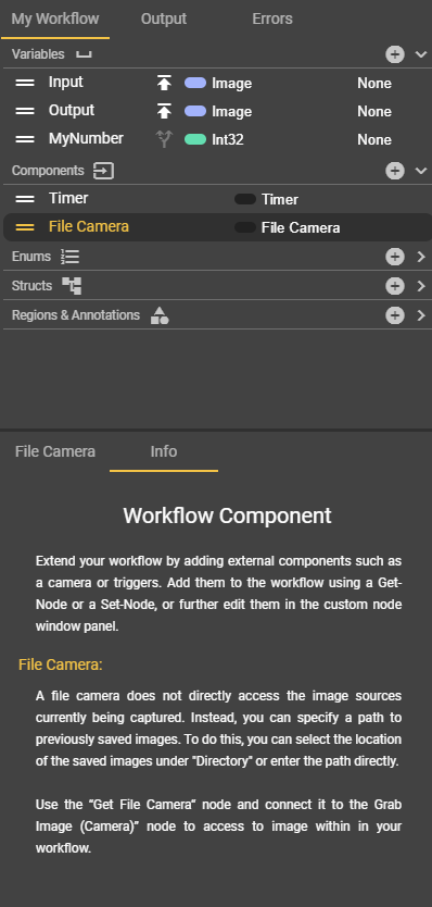
Image Tab
In this tab, you can configure annotations and display the last image captured using a variable.
Further information on configuring annotations can be found in the Image Editor section.