Digital Input / Output
In addition to communication protocols, VISIONWEB can also respond to digital inputs and outputs. This allows workflows to be initiated or controlled not only via messages or network protocols, but also directly via hardware signals.
The evoVIU camera currently has one digital input and two digital outputs that are routed to the outside.
The digital input serves as a trigger, allowing external sensors or controllers (e.g., PLCs, light barriers, or buttons) to interact directly with the camera. Events can thus be used reliably and in real time as triggers for workflows.
The digital outputs can be switched specifically from within a workflow. In addition to status messages or feedback signals, they can also directly control external lights or actuators. This allows, for example, inspection areas to be illuminated or machine statuses to be visually signaled.
In this way, the camera, lighting and external peripherals can be seamlessly integrated into existing automation environments.
Digital Input
The digital input in Visionweb is typically used to initiate a trigger event in the workflow. As soon as a desired voltage edge (rising or falling) is present at pin 5 of the 5-pin M12 connector, the corresponding event is activated and the connected flow is started.
The digital input is created under Components using the "+" symbol and can then be selected in the context menu of the Event Graph and connected to flows. This allows external signals, e.g., from a PLC, a button, or a light barrier, to be integrated directly into the workflow logic. More information is available at Hardware-Events.
Digital Output
The two digital outputs of the evoVIU camera can be controlled directly from a workflow. This allows external devices or systems to be switched directly. Typical applications include outputting status signals to a PLC, controlling relays or actuators, or controlling external lighting.
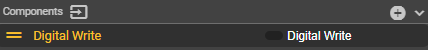
In VISIONWEB, the output is implemented using the Digital Write component. This can be easily created under Components using the "+" symbol.
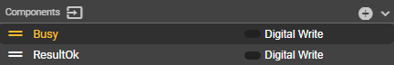
The created outputs can also be individually renamed – either according to their physical pin number (e.g., Pin2, Pin4) or according to their function in the workflow (e.g., ResultOk, Busy). This keeps the assignment clear and understandable for the user.
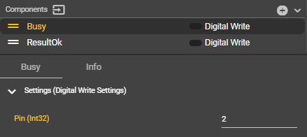
To configure the component, the corresponding pin number can then be entered. Currently, only pins 2 and 4 are possible.
Using the Set Pin node in the Event Graph context menu, the desired pins can be connected to flows for flexible use.
The following example demonstrates the use of an image acquisition workflow combined with the control of external lighting:
Before image capture, an output is activated via Digital Write to turn on a connected lamp.
After capture is complete, the pin is reset, turning off the light.
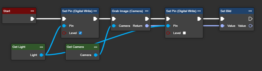
This direct connection allows outputs to be linked to conditions in the workflow—for example, to generate an OK signal upon successful image analysis or to activate a warning light in the event of an error. Lighting can also be switched on only during image acquisition to ensure optimal recording conditions.