GigE Vision
This function enables the integration and control of external GenICam-compatible cameras (e.g., Basler network cameras) directly within the evoVIU workflow. By utilizing the GigE Vision standard, cost-effective external cameras can be flexibly used as an additional image source.
Note:
Currently, GigE Vision connectivity in the evoVIU context is primarily used with cameras from Opto Engineering. Unless otherwise stated, the following information refers to these devices and their tools (e.g., OECS).
Requirements
The camera must support the GigE Vision / GenICam standard.
A suitable GenTL producer (driver) must be installed in the system.
The camera should generally be pre-configured using the manufacturer's tool, e.g.:
OECS (Opto Engineering Camera Software) for opto-engineering cameras
other manufacturer tools for cameras from other manufacturers
For opto-engineering setups, only one control unit can be actively connected to the camera at a time (either via VISIONWEB or via OECS, not both simultaneously).
GigE Vision Camera
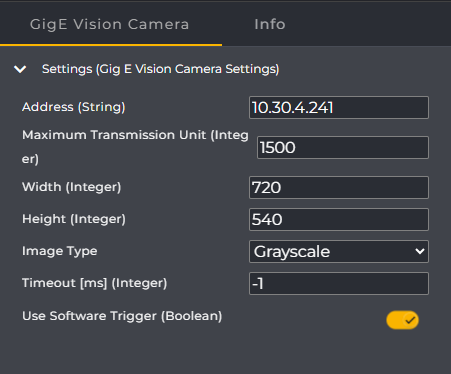
The GigE Vision Camera component offers a set of standard parameters. The following information is particularly required for successful use:
Parameter | Type | Description | Example |
|---|---|---|---|
Address | String | Camera IP address. The address should be determined using the respective manufacturer's tool (for Opto Engineering, for example, via OECS – the tool has an enumerate function to find available cameras). | 10.30.3.241 |
Maximum Transmission Unit | Interger | The MTU (Maximum Unit Size) is a property of the network used (e.g., the Ethernet connection) and determines the maximum size of a data packet. The tool typically sends one image line per packet. If the MTU is misconfigured, data packets may be dropped—in which case no images or only corrupted images may arrive. The correct MTU configuration should be ensured via the manufacturer's tool or the network configuration. | 1500 |
Width | Integer | Image width in pixels. This corresponds to the camera's resolution. Only a resolution supported by the camera may be used – otherwise errors will occur. | 720 |
Height | Integer | Image height in pixels. Corresponds to the camera's resolution. As with "Width", a value supported by the camera must be used. | 540 |
Image Type | ImageType | Describes whether the captured image is a color or grayscale image. This value depends on the actual camera used and its pixel format (e.g., Mono8, RGB8). | Verfügbare Werte:
|
Timeout [ms] | Integer | Specifies the time interval after which the request should be aborted. The value "-1" means: Wait indefinitely until an image is available. | 1000 |
Use Software Trigger | Boolean | Indicates whether image acquisition is performed via software trigger or in free running mode. For typical evoVIU workflows, the use of the software trigger is recommended. |
Step-by-Step instruction
To address an external camera in the workflow, you must first define it as a component.
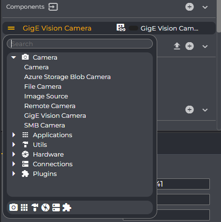
In the Components section, click the "+" symbol. Select GigE Vision Camera from the context menu.
In the newly created component, you can identify and configure the camera using parameters such as IP address.
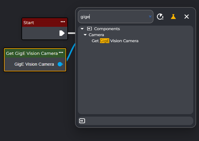
After configuring the component, integrate the camera into your workflow: In the workflow editor, search for the node "Get GigE Vision Camera" (or the name you assigned to the component).
Connect the output of this component to the "Grab Image (Camera)" node. In the Grab Image node, select the appropriate camera component. The captured image will be stored in a variable of type Image.
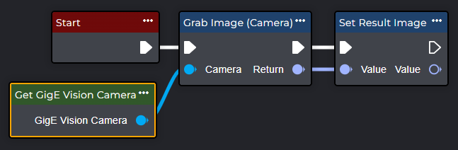
Congratulations – you have successfully stored an image in a variable within the workflow using GigE Vision. You can now use this variable in the subsequent processing nodes, f.e. in combination with https://evopro.atlassian.net/wiki/spaces/DVIU/pages/81952915
Tips & Hints
Free Running vs. Software Trigger
GenICam cameras often offer a free-running mode. Using a continuous streaming mode in your workflow is generally discouraged, as this can lead to increased system load at high frame rates. Instead, it is recommended to use targeted image capture via software triggers.
The software trigger can be set, for example, via OECS using the Trigger Source setting (important: Software). All trigger settings configured in the camera are generally stored persistently: The camera remembers the last setting – even if Use Software Trigger is set to false in the Component. Therefore, a complete change to the trigger behavior may need to be made again using the manufacturer's tool (e.g., OECS).
Recommendation:
Generally, set Use Software Trigger to true unless an explicit hardware trigger setup is in place.
Only set Use Software Trigger to false if a specific hardware trigger configuration exists.
Integration
The GenICam connection is currently implemented as a workflow component and is (still) not directly integrated into the global image source.
Fault diagnosis
If a camera cannot be found or no images are received, check in particular:
Device search via the manufacturer's tool (e.g., Enumerate in OECS) – is the camera detected on the network?
Use TLUpdate or similar functions to update the list of available devices in the transport layer.
Network MTU settings:
Is the MTU compatible with the camera/network settings?
An incorrect MTU can cause packet loss, resulting in incomplete images.
Resolution (Width/Height):
Are only values actually supported by the camera configured?
Trigger configuration:
Do the Use Software Trigger and the trigger parameters set in the manufacturer's tool match?
Is the free-running mode potentially generating excessive load?