RFC1006
The evoVIU camera supports RFC1006, a protocol that enables TCP/IP-based communication for industrial applications in accordance with TCP. It is primarily used in automation environments, for example in conjunction with PLC systems (e.g., Siemens S7).
Within the framework of RFC1006, the evoVIU uses PUT and GET commands to send or receive specific data:
With the PUT command, the camera actively transfers data – e.g., results or image information – to a connected control system.
The GET command allows data to be queried from the camera, such as status information, trigger states, or measured values.
Communication is binary and structured, usually via preconfigured addresses or data blocks within the target system. RFC1006 is particularly designed for deterministic and stable connections where clarity about every message sent or received is important.
RFC1006 communication is configured via the evoVIU web interface, where the IP address, port, and data structure (e.g., byte mapping) are defined. This interface is particularly suitable for integration into classic industrial control architectures.
Communication using direct PUT or GET commands is increasingly being avoided in modern control technology. The reason for this is the potential risk that incorrect entries could accidentally overwrite security-relevant bytes and functions.
Such operating errors can only be detected or prevented to a limited extent, if at all, via the VISIONWEB user interface.
We accept no liability for damage or malfunctions resulting from improper use and ignorance of this function.
We suggest a change to ISO-on-TCP or (7.7.0-en) OPC UA.
If the use of GET/PUT commands is unavoidable, we strongly recommend creating a separate data block in the control system that is clearly separated from security-relevant data blocks and functions. In addition, the camera system should be protected against unauthorized access by means of suitable user management.
Please note that the GET/PUT function must be explicitly enabled in the respective control system. Otherwise, this functionality will not be available.
Connection Parameter
Parameter | Type | Explanation | Example |
|---|---|---|---|
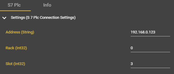
Address | Domain || IP - String | The destination address of the S7 controller. You will receive this information from the control engineer. | mysps.myfacory.de |
Rack | Integer | The rack ID is the rack position of the controller and is usually 0. You will receive this information from the control engineer. | 0 |
Slot | Integer | Slot number of the CPU in the rack. You will receive this information from the control engineer. | 3 |
Data Block | Integer | Data block number in the controller. | 5120 |
Start Address | Integer (Byte) | The byte range in which the data is stored in the controller. | 0 |
Example-DB5120
This is only an example data block – the data blocks can be listed individually. We strongly recommend separating the data blocks from security-related data blocks, i.e., introducing a number that cannot be chosen at random.
Byte | Bit | Type | Name | Example-Data |
|---|---|---|---|---|
0 | 0.0 | BOOL | Ready | FALSE |
0.1 | BOOL | Stop | FALSE | |
0.2 | BOOL | Trigger | TRUE | |
0.3 | BOOL | Reserve | FALSE | |
0.4 | BOOL | Reserve | FALSE | |
0.5 | BOOL | Reserve | FALSE | |
0.6 | BOOL | Reserve | FALSE | |
0.7 | BOOL | Reserve | FALSE | |
1 | CHAR | Sign 1 | “H” | |
2 | CHAR | Sign 2 | “A” | |
3 | CHAR | Sign 3 | “L” | |
4 | CHAR | Sign 4 | “L” | |
5 | CHAR | Sign 5 | “O” | |
6 | INT | Number | 240 | |
7…X | STRING | Info | “Hello World” |
Workflow Setup
Installation of an S7 PLC component
In Workflows, go to Components and select ➕.
Search for the “S7 Plc” component.
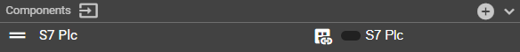
A new component called “S7 Plc” will appear. This can be renamed at any time.
Enter the connection data and make sure that it has been entered correctly.
Open the context menu in your event graph by right-clicking.
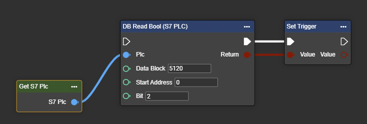
Search for “Get S7 Plc”.
The S7 Plc component has been successfully created and can now be used with the various PUT and GET commands in the workflow.
Reading and writing data in the database
The following workflow is shown symbolically using the upper data block as an example. This can be customized at any time—it is only used for illustration purposes. The Literal node is only used to show the data that is used in the individual Write and Read commands.
Reading the Bool “Trigger” in the DB5120 in byte 0 and bit 2
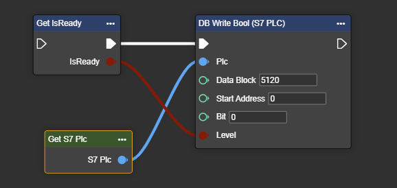
Reading the Bool “Read” in the DB5120 in byte 0 and bit 2
Byte | Bit | Type | Name | Data | Data | |
|---|---|---|---|---|---|---|
0 | 0.0 | BOOL | Ready | FALSE | >>> | TRUE |
Reading characters “character2” & “character3” in DB5120 in bytes 2 and 3
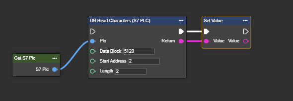
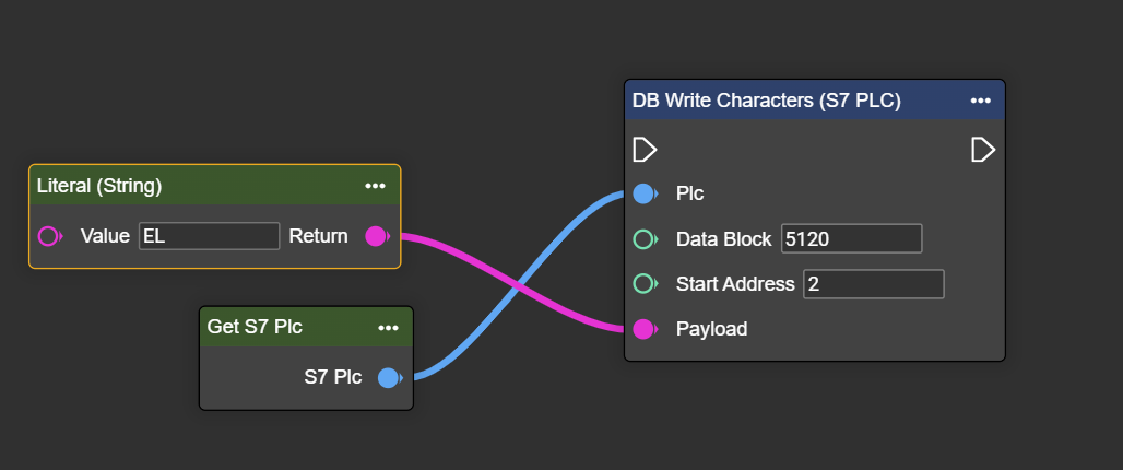
Setting the characters “Character2” & “Character3” in the DB5120 in bytes 2 and 3
Byte | Bit | Type | Name | Data | Data | |
|---|---|---|---|---|---|---|
2 | Char | Sign 2 | “A” | >>> | “E” | |
3 | Char | Sign 3 | “L” | >>> | “L” |
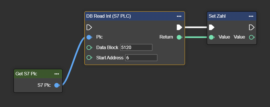
Reading the integer “number” in DB5120 from byte 6
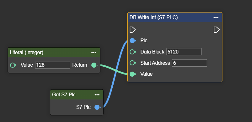
Setting the integer “number” in DB5120 from byte 6
Byte | Bit | Type | Name | Data | Data | |
|---|---|---|---|---|---|---|
6 | Integer | Number | 240 | >>> | 128 |
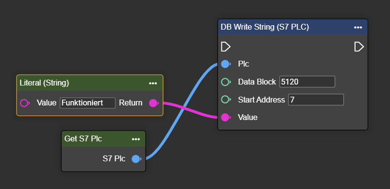
Reading the string “Info” in the DB5120 starting at byte 7
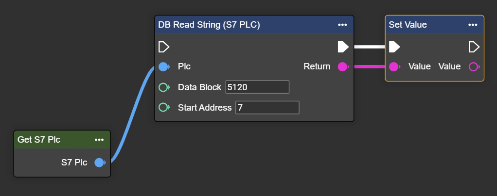
Setting the string “Info” in the DB5120 starting at byte 7
Byte | Bit | Type | Name | Data | Data | |
|---|---|---|---|---|---|---|
6 | Integer | Number | “Hello Wordl” | >>> | “Working” |
S7 Plc Trigger
With the S7 PLC trigger component, you can also receive cyclical notifications about data changes within the workflow. For this, in addition to a fully configured component in the workflow, you need the Trigger node, which refers to your S7 PLC trigger component.
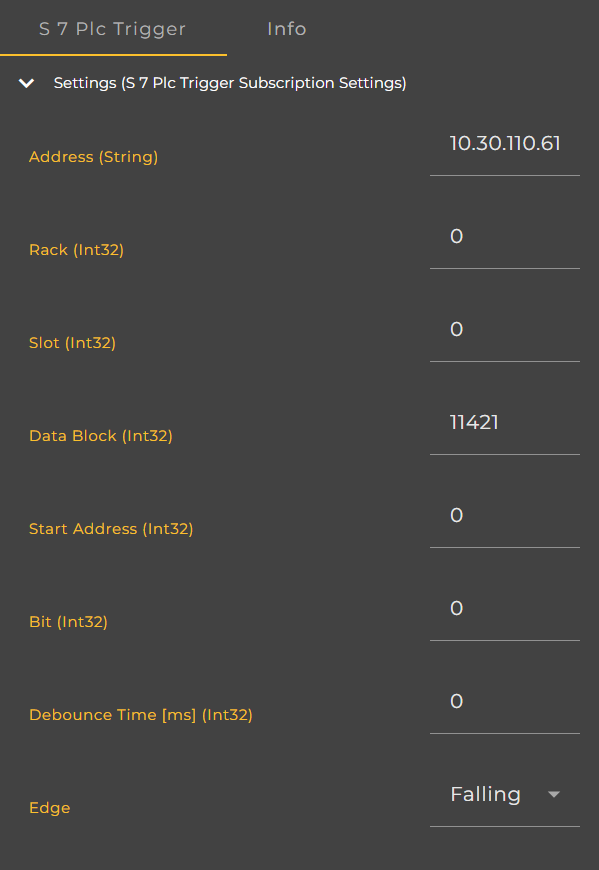
Connection parameters
Parameter | Type | Description | Example |
|---|---|---|---|
Address | Domain || IP - String | The target address of the S7 controller. You will receive this information from the control technician. | mysps.myfacory.de |
Rack | Int32 | The Rack ID is the rack position of the controller and is usually 0. You will receive this information from the control technician. | 0 |
Slot | Int32 | CPU slot number in the rack. You will receive this information from the control technician. | 3 |
Data Block | Int32 | Data block number in the controller. | 5120 |
Start Address | Int32 | The byte range in which the data is located in the controller. | 0 |
Bit | Int32 | The bit you want to read. | 0 |
Debounce Time | Int32 | Allows you to define a period after receiving a trigger signal during which new trigger signals are ignored. This setting helps prevent multiple responses to unstable/noisy electrical signals. | 5000 |
Edge | TriggerEdgeType | Determines whether to react to a rising or falling edge of the signal. | Possible values:
|
Workflow Setup
Installation of an S7 PLC trigger component
In Workflows, go to Components and click ➕.
Look for the “S7 Plc Trigger” component.
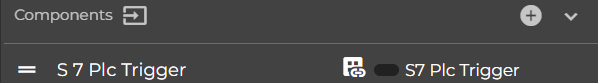
A new component named “S7 Plc Trigger” will appear. This can be renamed at any time.
Enter the connection details and make sure they are spelled correctly.
Right-click on your event graph to open the context menu.
Search for “Trigger (S7 Plc Trigger)”.
The S7 Plc Trigger component has been successfully created and can now be used in the workflow.