Contour
Filter
Sobel
Applies the Sobel operator – calculates gradient magnitude and highlights edges and intensity changes.
The Sobel filter highlights edges by measuring brightness changes in the image. It calculates gradients in the x- and y-directions and combines them to create an edge strength. This makes object outlines visible, robust against slight noise.
Flow
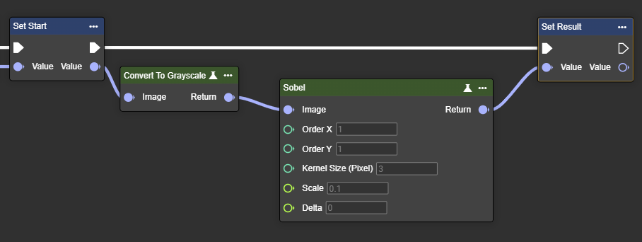
Parameter set
Parameter | Type | Description | Value range | Effect Min | Effect Max |
|---|---|---|---|---|---|
Image | Image | Requires a grayscale image. This can be created by using the "Convert To Grayscale" node. | 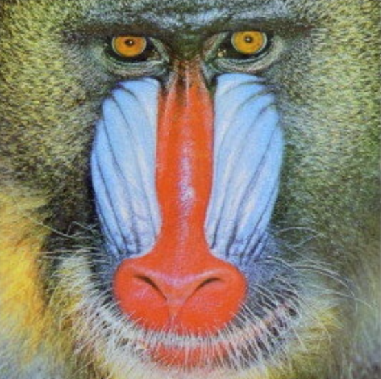 | 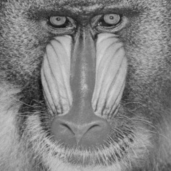 | |
Order X | Int32 | Specifies the gradient order in the x-direction. | 0…2 | 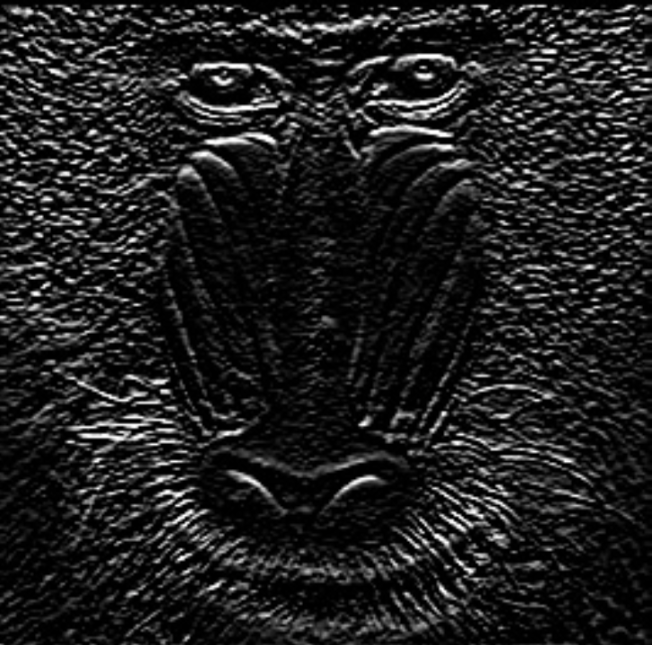 | 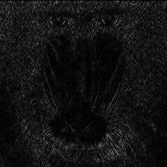 |
Order Y | Int32 | Specifies the gradient order in the y-direction. | 0…2 | 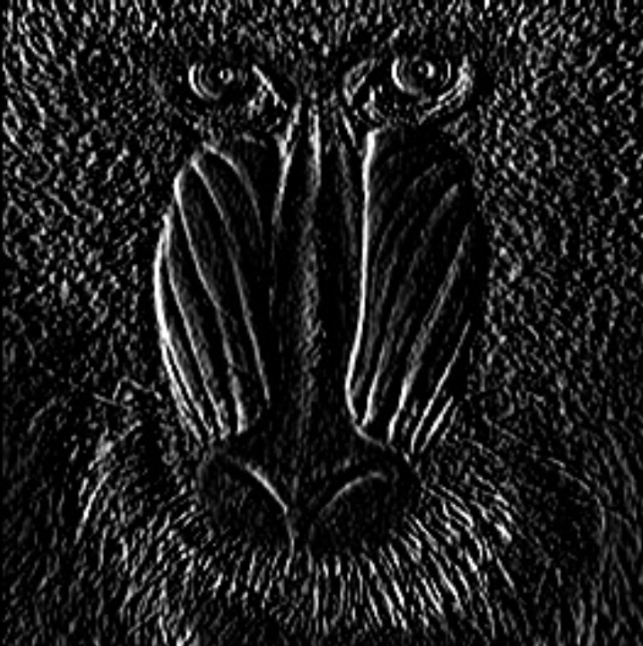 | 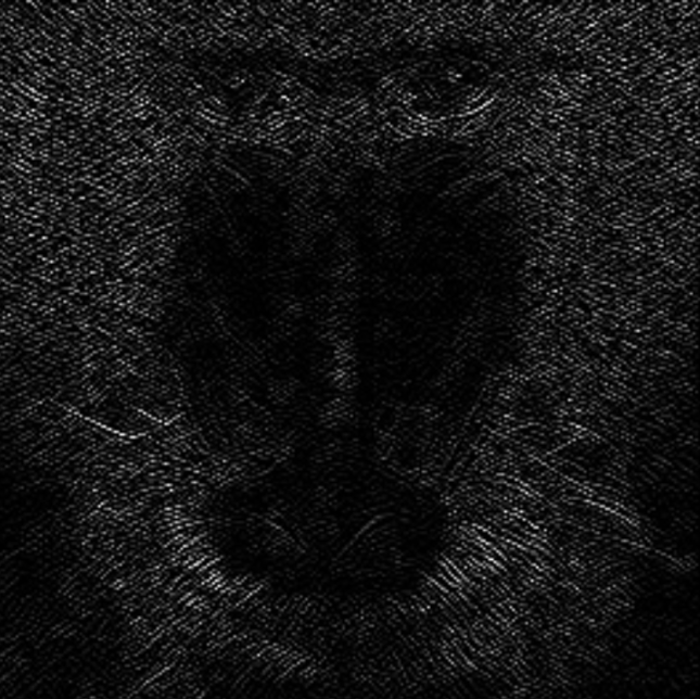 |
Kernel Size (Pixel) | Int32 | A high value increases the kernel size for calculating larger surface gradients. The size of the extended Sobel kernel must be 1, 3, 5, or 7. | 1,3,5,7 |  | 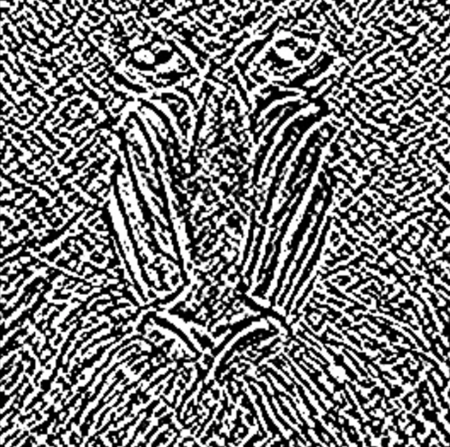 |
Scale | Single | Scaling factor applied to the calculated gradient. | >0.1 | 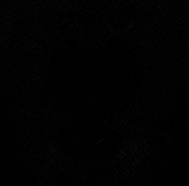 | 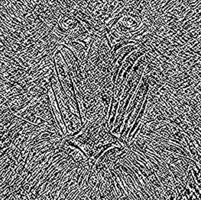 |
Delta | Single | Value added to the calculated gradient. | 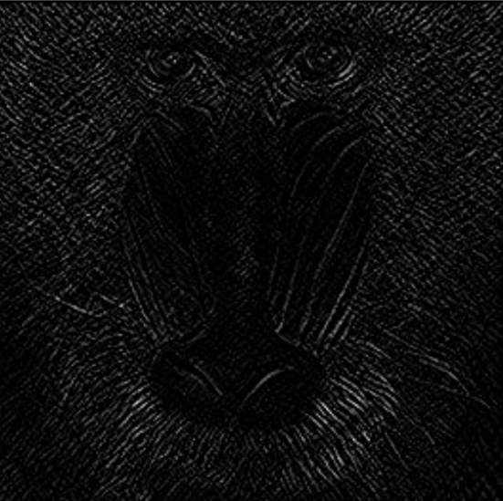 | 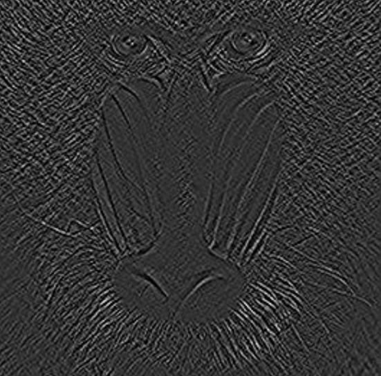 |
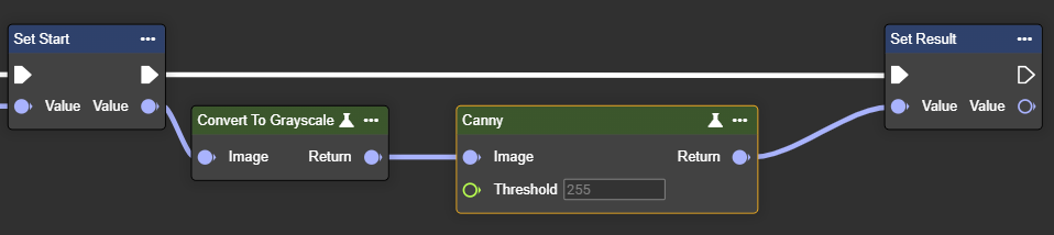
Canny
Applies the Canny edge detection algorithm – detects edges based on intensity gradients in the image.
The Canny detector detects edges with exceptional precision through multi-stage processing (smoothing, gradient, non-maximum suppression, and hysteresis). It delivers thin, clear contours and reliably suppresses noise. This makes it suitable for precise edge analysis and complex scenes.
Flow
Parameter set
Parameter | Type | Description | Value range | Effect Min | Effect Max |
|---|---|---|---|---|---|
Image | Image | Requires a grayscale image. This can be created by using the "Convert To Grayscale" node. | | | |
Threshold | Single | The value must be between 0 and 255. Higher values increase edge sensitivity, potentially detecting more edges. | 0…255 | 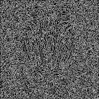 | 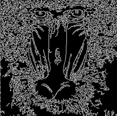 |
Laplacian
Applies the Laplace operator – calculates second derivative and enhances areas with rapid intensity changes.
The Laplacian filter uses the second derivative and marks edges with sharp intensity changes. It detects edges regardless of their direction. Because it is sensitive to noise, it is often combined with prior smoothing.
Flow
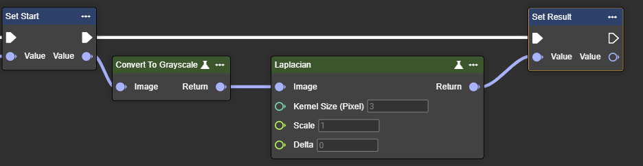
Parameter set
Parameter | Type | Description | Value range | Effect Min | Effect Max |
|---|---|---|---|---|---|
Image | Image | Requires a grayscale image. This can be created by using the "Convert To Grayscale" node. | | | |
Kernel Size (Pixel) | Int32 | The value must be positive and odd. A high value increases the kernel size for calculating larger surface gradients. | 1,3,5,7 | 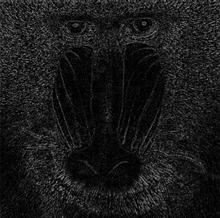 | 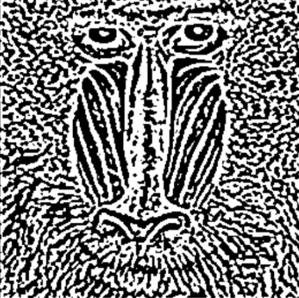 |
Scale | Single | Scaling factor applied to the calculated gradient. | >0.1 | 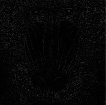 | 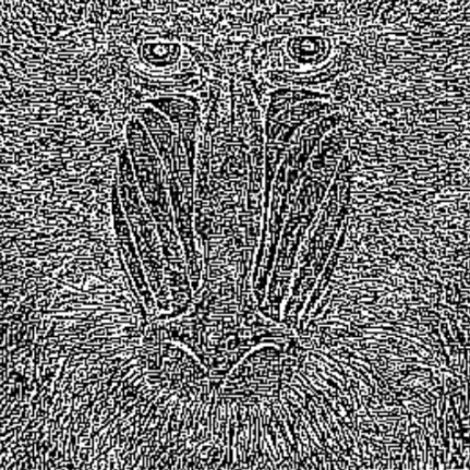 |
Delta | Single | Value added to the calculated gradient. | 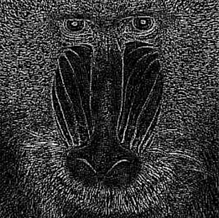 | 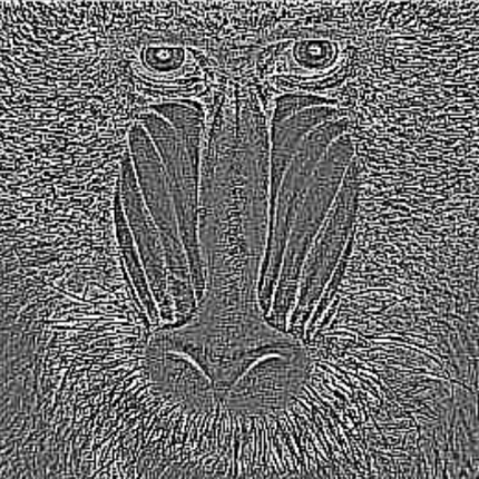 |
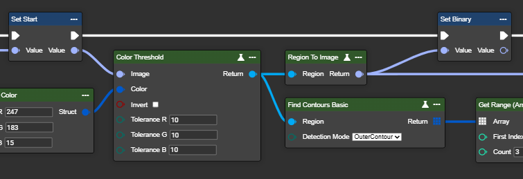
Find Contours Basic
This node detects and outlines contours (white areas) in a binary image. Suitable inputs include the Binary Threshold, Adaptive Threshold, Color Threshold, Canny, or other methods that generate a binary image from a grayscale image. Three modes are available: Inner Contour, Outer Contour, or Both Contours – these allow the inner and outer contours of a surface to be detected. The detected contours can then be used for further processing.
Flow
Parameter set
Image preparation | Type | Description | Value range | Before | Thereafter |
|---|---|---|---|---|---|
Image | Image → Region | Converting an image into a region using the Color Threshold node. The desired color is previously defined in the Make Color node—for example, yellow. |  | 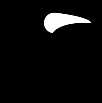 | |
Image | Image → Region | The same conversion of an image into a region using the Color Threshold node. The desired color is previously defined in the Make Color node—for example, white. | |  | |
Parameter | Type | Description | Value range | Before | Thereafter |
Detection Mode | InnerContour | Detects only the inner contours of objects. This mode is useful when you want to focus on closed shapes within a binary region and ignore the outer boundary. | |  | |
OuterContour | Detects only the outermost contours of objects. This mode is suitable for isolating the outer boundaries of objects without considering nested structures. | |  | ||
BothContours | Detects both the outermost contours and all nested inner contours. This mode is ideal for analyzing hierarchical relationships between contours, for example, when objects are enclosed by other objects. | | 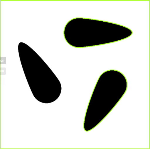 |
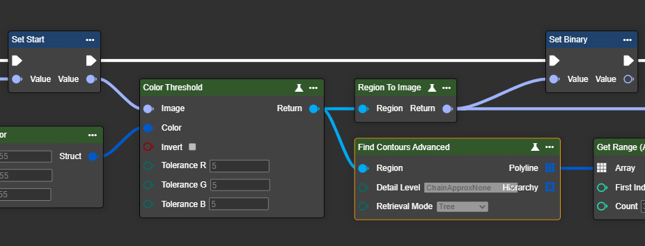
Find Contour Advanced
This node detects and outlines contours (white areas) in a binary image. For it to work, the objects must be white – if necessary, the Invert Pixel node can be used for preprocessing. The detected contours are output sorted from largest to smallest and can be used for further processing.
Compared to the Find Contour Basic node, the Find Contour Advanced node allows you to control the process and thus the processing speed, as well as to specifically influence the sorting of the output contours.
Flow
Parameter set
Image preparation | Type | Description | Before | Thereafter |
|---|---|---|---|---|
Image | Image → Region | Converting an image into a region using the Color Threshold node. The desired color is previously defined in the Make Color node—for example, yellow. | | |
Image | Image → Region | The same conversion of an image into a region using the Color Threshold node. The desired color is previously defined in the Make Color node—for example, white. | | |
Parameter | Type | Description | Before | Thereafter |
Detail Level | ChainApprxNone | Saves all points of the contour (very accurate, but memory intensive). | | |
ChainApproxSimple | Reduces points to a minimal representation (e.g. for a rectangle only 4 corner points). | | | |
ChainApproxTc89L1 | A Douglas-Peucker-like method that simplifies contours with fewer points (more accurate but more compact). | | | |
ChainApproxTc89Kcos | Similar to Tc89L1, but uses a different heuristic for simplification (often even smoother approximation). | | | |
Retrieval Mode | ListByArea | Returns all contours and sorts them by area (from largest to smallest). | | |
External | Returns only the outer contours, inner structures are ignored. | | | |
Ccomp | Creates a two-level hierarchy: outer contours and their directly contained holes. | | | |
Tree | Builds a hierarchy of contours (e.g. outer contour and holes in it). | | |
Notes on the parameter set:
Detail Level
In 90% of cases, ChainApproxSimple is the right choice. It's fast, memory-efficient, and provides stable vertices/vertices for most applications.
The other options are useful in the following situations:
ChainApproxNone– when every pixel point is needed (e.g., precise lengths/perimeters on a pixel-by-pixel basis, downstream smoothing/resampling), which, however, consumes memory and time.ChainApproxTc89L1 / Tc89Kcos– when contours are long or noisy and a compact, smooth representation is required (shape matching, tracking). Kcos is often a bit smoother, while L1 is a bit more angular.
Retrieval Mode
For most applications, External is the recommended setting because it reliably detects the external object contours and hides internal structures.
If the entire hierarchy (e.g., outer contour and all holes/subcontours) needs to be captured,
Treeis suitable.Ccompis sufficient for a simplified outer/inner relationship.ListByAreais useful if the largest or smallest contours need to be processed further.
👉 Recommendation: ListByArea or External as standard, Tree if internal structures are important.
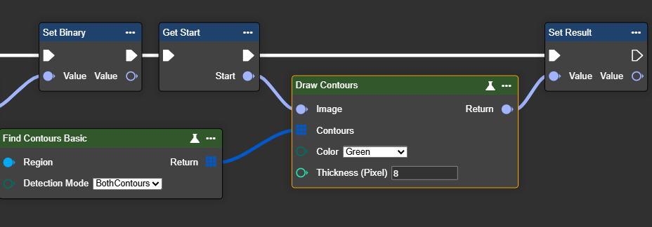
Draw Contour
This node allows contours to be displayed directly in the image. This makes it easier to visualize and verify the outlines of previously detected objects or regions.
Important: Before using this node, contours must first be found. To do this, use the Find Contours node and connect its output to the Contours input of this node.
Flow
Parameter set
Parameter | Type | Description | Input | Return |
|---|---|---|---|---|
Image | Image → Input | The image in which you want to draw the outlines. |  | 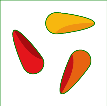 |
Contours | Polyline Array | A polyline is a continuous line consisting of several connected segments stored in an array that represent the outlines or edges of contours in an image. To do this, a “Find Contours Basic” or “Find Contours Advanced” node must first be used. | ||
Color | Beispiel 1: Green | Choose a color to highlight the outlines. In this example, the outlines are drawn in green. Other colors:
| | |
Beispiel 2: Red | Choose a color to highlight the outlines. In this example, the outlines are drawn in red. Other colors:
|  | ||
Thickness (Pixel) | Int32 | Select the line thickness. A higher number results in a thicker outline. The value must be greater than 1. |  |  |
Get Contour By Index
Retrieves contours from a polyline array for a specified index range. Indexing is done by distance from the image origin (0,0), with the nearest contour drawn first. This requires a previous contour search using the "Find Contours Basic" or "Find Contours Advanced" node.
In this way, individual or multiple contours can be specifically selected for further processing.
Flow
Paramerter set
Parameter | Type | Description |
|---|---|---|
Contours | Polyline Array | A polyline is a continuous line consisting of several connected segments stored in an array that represent the outlines or edges of contours in an image. To do this, a “Find Contours Basic” or “Find Contours Advanced” node must be used beforehand. |
Min Index | Int32 | Minimum index value of the contours to be retrieved. The minimum value is contour length 0. |
Max Index | Int32 | Maximum index value of the contours to retrieve. The maximum value is contour length - 1. |
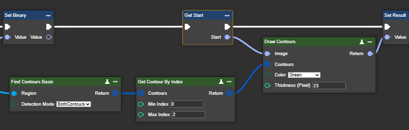
Get Contour By Area
This node filters contours by area, sorting from largest to smallest. This node is best suited if you're looking for a specific area size or want to filter out all contours. A previous contour search using the "Find Contours Basic" or "Find Contours Advanced" node is required.
Flow
Parameterset
Parameter | Type | Description |
|---|---|---|
Contours | Polyline Array | A polyline is a continuous line consisting of several connected segments stored in an array that represent the outlines or edges of contours in an image. To do this, a “Find Contours Basic” or “Find Contours Advanced” node must be used beforehand. |
Min Area Pixel | Int32 | Minimum area size of the contours to be included. The minimum value is 0. |
Max Area Pixel | Int32 | Maximum area size of the contours to be included. |
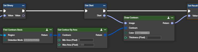
Contours to Region
This node converts contours into a binary image (region) – usable as a mask for further processing. This requires a previous contour search using the "Find Contours Basic" or "Find Contours Advanced" node.
Flow
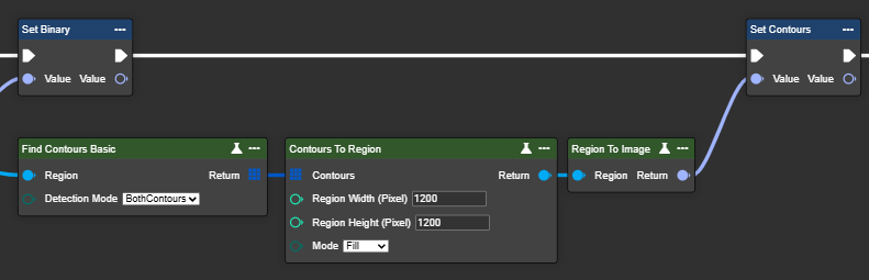
The return type is a Region. This data type can be converted back to an image format or the image data type using the "Region To Image" node.
Parameter set
Parameter | Type | Description | Example 1 | Example 2 |
|---|---|---|---|---|
Contours | Polyline Array | A polyline is a continuous line consisting of several connected segments stored in an array that represent the outlines or edges of contours in an image. To do this, a “Find Contours Basic” or “Find Contours Advanced” node must be used beforehand. | ||
Region Width (Pixel) | Int32 | The width of the binary image, which determines the horizontal size of the mask or region. |
Width = 600  |
Width = 1200  |
Region Height (Pixel) | Int32 | The height of the binary image, which determines the vertical size of the mask or region. | ||
Mode | Enum: Fill | The contours are filled with white color to create a solid area. | | |
Enum: Border | Only the edges of the contours are drawn in white. | 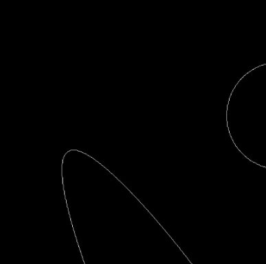 | 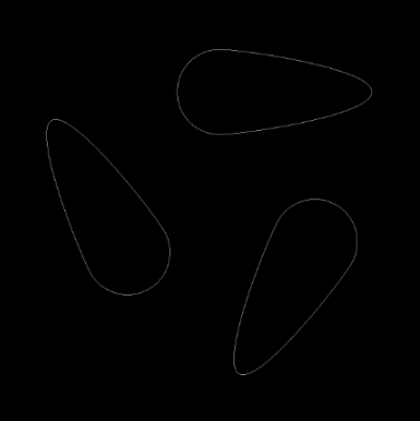 | |
Return | Region | Binary image processed in black and white. |